
IPFusion PLC Devices
The IPFusion PLC Devices integrated system provides door control via programmable logic controllers.
Definitions
PLC — Programmable Logic Controller.
Setup
See the Data Servers page for information on configuring driver communication.
Compatibility
- Omron FINS Ethernet
- Modbus
- Allen-Bradley
Prerequisites
| Software | Minimum Version |
|---|---|
| .NET Framework | 4.7.2 |
Communication Configuration
In the integrated system configuration panel, you will find the Communication Settings. The below information is required under Device Settings.
You can add multiple PLC devices to the communication configuration. For each device, you must set:
| Name | A name to describe the device being connected to. |
| Device Type | The type of device being connected to. |
| Network Address | The address of the device on the network you wish to connect to. |
| Network Port | The port on used to connect to the PLC device. |
| Source Network Address Number | Specifies the address number of the source network. The valid range is 0 to 127. |
| Source Node Number | Specifies the number of the source node. The valid range is 0 to 254. Note: Setting the
Source Node Number to 0 automatically assigns the node
number of the Omron device based on the 4th octet of its own
IP address. |
| Destination Network Address Number | Specifies the address number of the destination device. The valid range is 0 to 127. |
| Destination Node Number | Specifies the node number of the destination device. The valid range is 0 to 254.
Note: When a Destination Node Number of 0 is entered, it
will take the 4th octet of the target IP
address. |
| Destination Unit Number | Specifies the number of the destination device unit number. The valid range is 0 to 255. |
| Name | A name to describe the device being connected to. |
| Device Type | The type of device being connected to. |
| Network Address | The address of the device on the network you wish to connect to. |
| Network Port | The port used for the connection to the device. |
| Slave Address | The address for the specific slave device to be connected to. |
| Name | A name to describe the device being connected to. |
| Device Type | The type of device being connected to. |
| Network Address | The address of the device on the network you wish to connect to. |
| Network Port | The port used for the connection to the device. |
| Path | The route a message takes through the network to reach its destination. |
| Timeout Interval (msec) | The time the system waits for a device response. |
| Heartbeat Interval (msec) | The frequency at which the system sends a heartbeat message to verify communication with the device. |
- All unacknowledged element alarms are acknowledged.
- If a new element alarm comes in, the existing alarms remain acknowledged, the new alarm is unacknowledged.
- All element alarms are reset.
- If the underlying visibility expression is still true, the alarm is re-triggered.
Assets
Custom Assets
In the PLC Devices integrated system, custom asset types are created in the integrated system settings. These settings define the visuals for the asset based on different conditions, and how its icon appears. Once these icons are created, they can be dragged from the Toolbox to a Map.
- Masked — This element shows when the asset's true state has been masked over.
- No Communication — This element shows when Runtime cannot get status for the asset's status tag. This element cannot be deleted.
- Selected — This element shows when the asset is currently selected to provide visual feedback for the Runtime operator.
You can see how to create asset types here.
Required Property Grid Fields
| Asset Type | The type of asset as defined in the integrated system settings. |
| Associated Assets | The assets associated with the PLC device. |
| Command Address | The address of the tag on the PLC device that commands from this asset are written to. |
| Device | The PLC device this asset and its tags are located on. |
| Polling Interval | The frequency of which Runtime polls the device for this asset's status. |
| Status Address | The address of the tag on the PLC device that the status for this asset is read from. |
Asset Type Settings
| Property | Description |
|---|---|
| Asset Type ID | The unique identifier of the asset type. |
| Asset Type Name | The name of the asset type. |
| Background Color | The background color of the asset. |
| Caption Color | Select Edit Caption Colors to configure the color settings of the asset. |
| Caption blinks when asset is in Alarm | Check this option to have the caption text blink when the asset is in an alarmed status. If caption text flashing is also enabled, this will override it and the text will blink instead. |
| Icon Size | The size of the asset. Note: When Scale
Elements with Icon Size is enabled, all
elements in the icon scale proportionally when the asset
icon size changes. When disabled, elements keep their
original size and are not affected by asset icon size
changes. |
Edit Caption Colors
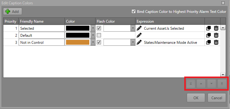
- To configure the color of the caption on the icon, click on the Edit Caption Colors button.
- Click Add and create a new Caption Mode. Fill in the chart according
to the different fields:
Property Description Bind Caption Color to Highest Priority Alarm Text Color When enabled, the caption color is determined by the highest-priority active alarm type across all currently visible layers. The asset's caption will use the Text Color of the alarm as defined in Alarm Management. Active alarms will override any expressions defined below regardless of priority. Priority The priority of the color expression. A lower number indicates a higher priority (1 is highest, 99 is lowest). Note: If multiple expressions are true in Runtime, the higher priority color will display.Friendly Name A name used to identify or describe the expression. Color The color that the caption will show in Runtime. Flash Color A checkbox that determines whether the Flash Color is used. Expression The expression that must evaluate to true for the specified color to be displayed. Note: If the expression is blank, it will always evaluate to true. - After creating the Caption Mode, adjust its priority using the
arrows to set its placement.
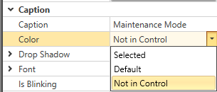
- Find the new Caption Mode under Caption in the
Properties grid.
Element Alarms
Each element can optionally be bound to an alarm. The alarm is triggered when the element is visible. The settings for this are in the element properties:
| Alarm Type | The type of alarm which is fired when this element becomes visible. Note: When alarm
type is None, the element will be visible. |
| Bind to Alarm | Check this to bind this element to an alarm when it is visible. |
| Is Latched | Check this so that the Runtime operator must acknowledge and reset the alarm before it is cleared from the asset. |
| Include in Activity Log | The reporting logs show all of the visible elements in the status string for the
asset. Check this box to include the symbol while
visible. Note: Checking the Include in
Activity Log box will write the
element's Logging Description to
the Activity Log. If the Logging
Description is left blank, the
Friendly Name will be used
instead. |
Element Appearance
An element can have its appearance modified for how it is displayed on the asset icon.
| Property | Description |
|---|---|
| Fill Color | The color which fills the shape/symbol. |
| Flash Fill Color | If Flash is enabled, the symbol will flash between its default Color and this one. |
| Line Color | The color of the shape outline. |
| Flash Line Color | If Flash is enabled, the symbol's outline will flash between its default Color and this one. |
| Text Color | The color of the text. |
| Flash Text Color | If Flash is enabled, the text will flash between its default Color and this one. |
| Is Bound to Alarm Colors | When enabled, the symbol or text will use the color scheme defined by its associated
alarm state. Note: This can only be enabled if
Bind to Alarm is
checked. |
| Is Flash Enabled | When enabled, the symbol, image, or text will alternate between its default color and the Flash settings to create a flashing effect. |
Element Identification
Elements have two main identifiers:
| Friendly Name | A name you can define to easily identify this element. This is the name which appears in both the Elements pane and in Workflow browsers. |
| ID | The unique identifier for this element. Note: ID is read only. |
| Logging Description | The description of the element that will be written to the activity log if Include in Activity Log is checked. |
Element Layout
The general layout of a specific element can be configured in its settings.
| Height | The height of this element in pixels. |
| Width | The width of this element in pixels. |
| X | The X position of the left of the element. |
| Y | The Y position of the top of the element. |
Required Element Settings
When creating a custom asset type, the elements which are displayed can be any of the below types. Multiple elements of varying types can be added to a single asset type. They can each have their visibility changed separately to indicate status to the Runtime operator. See the Element Visibility section for further information.
| Element Type | Required Properties | Description |
|---|---|---|
| Image
|
Choose Image — Select an image resource from the project to be
displayed within this element. Note: Choose Image
Flash is available for elements that are
images. When enabled, the element will alternate between
the default image and the selected flash image whenever
the element is in an alarm state. |
An image resource to be displayed on the asset icon. |
| Text
|
Text — The text to be displayed. | Some text to be displayed on the asset icon. |
| SVG (Advanced)
|
SVG Image — The image to be imported from the File Explorer. | An SVG image to be displayed on the asset icon. |
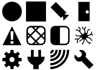
| Symbol (Recommended)
|
Select a symbol to be displayed from the symbols included in Designer. | A symbol to be displayed on the asset icon. |


Element Visibility
Each element added to an asset type can be set to visible/invisible based on a set of conditions. For more information, go to the Visibility Expression Editor page.
Interlock
Required Property Grid Fields
| Command Address | The tag address used to send commands. |
| Status Address | The tag address used to receive a status. |
| Device | The PLC Device this interlock is connected to. |
| Polling Interval | How frequently in milliseconds this interlock is polled for updates. |
Supported States
| Fault | An issue has been detected in a connected asset. |
| Masked | The asset has been masked over its true state. |
| No Communication | Communication has been lost with the driver or asset. This status can
also occur if the communication configuration for the system or asset is
invalid. Note: This status is required in all status
tables.
|
| Normal | The asset is online and in its default state. |
| Word | The asset contains a specific word value.
|
| Word Range |
The asset contains a specific word value.
|
| Bitwise | The asset word value matches a configured bit mask.
|
See the Configure a Status Table page for more information on configuring status tables.
Supported Commands
| Mask | Mask the asset's true state. |
| Acknowledge | Acknowledge an asset alarm. |
| Reset | Resets the asset to its true hardware state. |
| Cancel | Deselects all selected assets. |
| New Note | Adding the New Note Command to your Command Table subscribes this asset to Notes, allowing an operator to attach Notes to this asset in Runtime. |
| Workflow Trigger | Allows users to trigger Workflows to create custom commands. |
| Write Word | Sets the asset to a specified word value.
|
See the Command Tables page for more information on configuring command tables.
Workflow Integration
System Commands
System commands are commands executed through Workflows at the system level. For more information about Workflows see the Workflows section.
Set Custom Attribute Value
This command sets the value of a custom attribute for a PLC device asset. This can only be used with custom assets.
| Asset(s) | The IDs of the assets which are having a value written to them. |
| Attribute Name | The name of the custom attribute which is being written to. |
| New Value | The value being written. |
Write Word to Command Address
This command writes a word to a PLC device asset.
| Asset ID | The ID of the asset which is getting a value written to it. |
| Value | The value being written. |
Asset Events
Asset events are events used to trigger Workflow actions on an asset level. For more information about Workflows, see the Workflows section.
Layer Changed
Triggered when the layer on an asset updates. Only one trigger will fire for Layer Changed even if multiple layers are changed at once.
- A layer is defined with no visibility expression.
- A layer is defined with a visibility expression that yields to false at startup.
- Asset has no layers at all.
Status Word Changed
Triggered when the PLC Status Word changes regardless of whether it creates an element change.